Installation informations
Design requirements
The lead-in chamfers on rods, shafts and bores must be provided for the different seals as shown in the illustration for each installation situation.
Plastic and elastomer sealing and wiper/scraper elements must not be pushed over sharp edges, thread crests, cross holes, grooves or rough surfaces. This aspect must be considered in the design phase or during construction.
If this is not the case, these points must be covered before installation.
General installation information
Components and tools must be cleaned before installation.
Sharp-edged tools must never be used during installation. Consider the effective direction when installing unidirectional elements.
On sliding rings and wipers/scrapers the parts may be greased or oiled.
On elastomeric parts and O-rings made from EPDM, SBR, IIR or CR, do not use mineral oil or grease, only silicone oil.
For shaft seals (particularly types 231; 233; 234 and 238), the groove (housing) must be degreased before installation. Grease or oil must not penetrate into the groove and between the O-ring and the profile ring during installation.
During final installation and when carefully joining the components, the contact surfaces between the seal and the mating surface may be greased or oiled to reduce the mounting forces.
Resizing can also be carried out through the mating surface (cylinder bore or rods). They must have a lead-in chamfer of sufficient size for this purpose.
When using oil or grease, make sure that the materials are compatible!
Installation of outer sealing elements in recessed grooves
When installing seals with an O-ring energizer in a recessed groove, first place the O-ring in the seal groove, then fit the sealing ring. With type 314 and 354 seals it may be convenient to install the sealing ring and O-ring together in one operation.
The use of assembly aids or tools is recommended for plastic seals.
… without assembly tool
If the lead-in chamfer on the piston is of sufficient size, the sealing ring can be installed directly. Sealing rings are easier to fit if they are heated to 80 to 100°C in oil, water or the oven. Do not exceed the maximum temperatures for the materials used.
The seal is resized with a resizing tool or a cylindrical tube; this requires a lead-in chamfer of sufficient size. The chamfer should be sized as shown in the design dimensions.
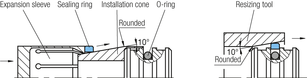
… with assembly tool
Special assembly tools consisting of installation cone, expansion sleeve and resizing tool are suitable for series installation of ‘outer acting seals’.
To avoid damage to the seal and component, the assembly tool should be made from a plastic with good sliding properties (e.g. polyamide, POM).
The sealing ring should be stretched as little as possible during installation and then only briefly. Therefore a thin-walled installation cone should be used.
The more quickly the installation process is completed, the better the sealing rings snap back to their original size in the groove. If the expansion for installation is not reversed quickly enough, the elements must be put back into shape with a resizing tool before final installation.
If the chamfering on the bore is long enough, installation is possible without pre-sizing.
Installation of inner sealing elements in recessed grooves
To install seals with an O-ring energizer in a recessed groove, first place the O-ring and then the sealing ring in the housing. With type 316 and 356 seals it may be convenient to install the sealing ring and O-ring together in one operation.
The use of assembly aids or tools is recommended for plastic seals.
… without assembly tool (seal folding)
Sealing rings with a large inside diameter can be installed without an assembly tool.
Installation begins with the O-ring. Then the sealing ring is folded into a kidney shape with no kinks. This shape makes it easy to place it in the groove.

Once in the groove, the ‘kidney’ is unfolded and reshaped to a circle by hand. Finally the seal must be resized, either with a resizing mandrel or with a resizing rod if the chamfering is long enough.
The disadvantage is that the loop cannot be fully reshaped and a ‘residual kink’ is left. This causes slight leakage, particularly with small diameters and low pressures, but this is reduced on run-in.
… with assembly tool
For series installation of ‘inner acting seals’ the use of assembly tools consisting of installation sleeve, compression mandrel and resizing mandrel is recommended.
The parts should be made from a plastic with a good finish and good sliding properties (e.g. Polyamide, POM) to prevent damage to the seals and components.
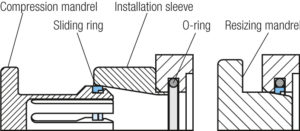
The sealing rings should be compressed as little as possible during installation and then only briefly. Therefore a thin-walled installation sleeve should be used.
The more quickly the installation process is completed, the better the sealing rings snap back to their original size in the groove. If the sealing ring projects too far inside due to the assembly deformation, the seal must be put back into shape with a resizing mandrel before final installation. If the chamfering on the rods is long enough, installation is possible without pre-sizing.
Assembly tools
Due to the different dimensions and specific application conditions, these assembly tools cannot be supplied as standard. They are available on request but a drawing of the relevant component is required.
Installation in open grooves
Split housings are installation-friendly and are generally recommended because the seal is not deformed.
Split housings are a requirement for flange-clamped and/or spring-loaded seals. The installation sequence should be suitable for the seal structure.