General design informations
Friction
IDG materials are primarily based on compounds which are structured on a polytetrafluoroethylene (PTFE) matrix and therefore have very low static and breakout friction.
This is because pure PTFE has a low coefficient of friction which decreases further under load.
Other factors affect the coefficient of friction. They include the mating surface material, its surface roughness and hardness, the sliding speed and the temperature and lubrication.
IDG PTFE based materials are characterized by chatter-free sliding characteristics.
Influence of the mating surface
The surface roughness and accuracy of form of the mating surface have a very strong influence on the development of leakage and the service life. Surfaces with the highest possible material ratio should be the aim. This is achieved by ultrafine grinding, honing and lapping. Rough edges and hollow edges are also smoothed. This is extremely important on hard mating surfaces in particular.
A surface smoothed by rolling or calendering can become uneven and wavy, which is very detrimental to seals made of high-performance plastic compounds.
For rotary and oscillating motion, the counter surface must be plunge-ground without any machine lead.
Surface roughness, material ratio
Surface roughness according to DIN EN ISO 4287
The seal and mating surface are always considered as a pair. The functional reliability and life of a seal is therefore greatly dependent on the surface finish of the mating surface.
Scratches, grooves, shrinkage cavities and concentric or spiral machining threads or grooves are unacceptable. Higher requirements must be laid down for the mating surfaces in dynamic than in static applications.
The parameters most commonly used to describe the fine surface texture (Rz, Rt and Ra) are defined in DIN EN ISO 4287. In some cases these parameters are insufficient by themselves and the material ratio (Rmr) should be specified.
The material ratio (Rmr) is vital for evaluation of surface finishes, as this parameter is determined by the profile form, which in turn results from the specific machining process.
Surface profiles

Ra 0,1 | Rz 1,0 | Rmr 70 %

Ra 0,2 | Rz 1,0 | Rmr 15 %
The graphic shows that the parameters Ra and Rz do not fully describe the profile and that on their basis an evaluation of the surface for its suitability for the sealing system is insufficient.
Protection from hydrodynamic drag
A hydrodynamic drag flow develops on linear bearings with a narrow gap between the stationary casing and the moving surface due to linear motion in the fluid. If the flow is ‘blocked’ by a seal, a pressure rise which can be many times greater than the system pressure is generated, particularly with ‘long’ movements.
For this reason the space in front of the seal should be as large as possible.
If this does not suffice, then it is necessary to provide a backflow channel (in the form of a spiral groove) or to fit MANOY® bearing rings with an angle cut split or bearing strips. This prevents critical pressure build-up upstream of the seal.
Smoothing, run-in
The mating surface is smoothed by the sealing and bearing elements during the running-in period.
However, short strokes in quick succession and oscillating movements promote the formation of unwanted run-in grooves. Extraneous vibration originating from a different point on the construction causes the same effect. To eliminate the formation of unwanted run-in grooves as much as possible, the mating surface should be hard.
Hardness of mating surface
In general, sealing element wear on hard mating surfaces is less than on soft material surfaces. There is a danger of run-in grooves being formed, particularly in rotary applications.
If the mating surfaces are not hard enough, contaminant scratches can also lead to damage to the sealing and bearing elements. Sooner or later this will cause leakage.
The minimum hardness should be over 58 HRC for linear motion and over 62 HRC for a rotary application.
General requirements
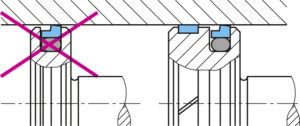
The lead-in chamfers on rods, shafts and bores must be provided for the different seals as shown in the illustration for each installation situation.
Plastic and elastomer sealing and wiper/scraper elements must not be pushed over sharp edges, thread crests, cross holes, grooves or rough surfaces. This aspect must be considered in the design phase or during construction.
If this is not the case, these points must be covered before installation.
Bearing, centering
Metal contact between piston, rods and casing must be prevented. Grooving due to starting up would damage the seal, bearing and wiper/scraper and lead to leakage.
The seal and the wiper/scraper are not suitable for bearing functions. Separate bearing elements with sufficient bearing capacity must be specified.
Lubrication, dry running
Nearly all IDG PTFE-based materials have a dryrun capability, but dry running reduces the life of the seal/mating surface system. A closed film of lubricant in the clearance gap reduces the coefficient of friction.
The lowest coefficient is obtained with hydraulic or lubricating oil. A film of lubricant also reduces heat generation in the clearance gap and extends the seal life.
Lifetime lubrication on installation is normally sufficient for applications such as pneumatic cylinders and guide rods.
Abrasive particles in the fluid
Particles are not generally the cause of leakage but they do generate significant wear on the seal/mating face system, leading to premature failure of the seal. The wear on a system is determined not only by the size of the suspended abrasive particles but also by their numbers.
With a typical lubricant film thickness of 0.5 μm, small particles float through but larger ones cause wear on seals and mating faces.
The number of particles should be minimized by design measures (e.g. filter system). The standards governing the qualification and quantification of fluid purity are ISO 4406 and NAS 1638.